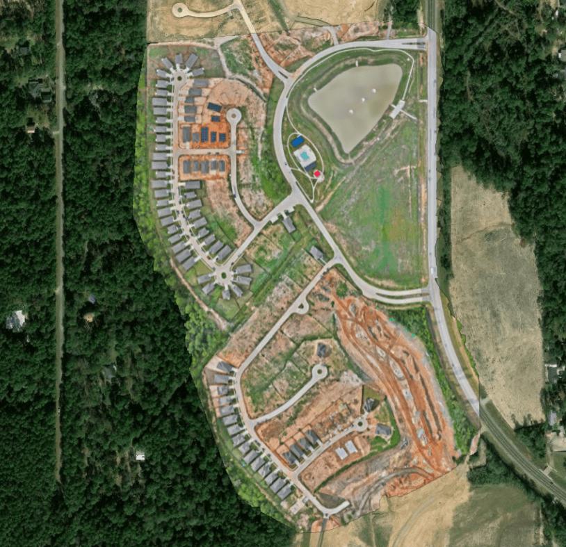
A drone mapping project can process perfectly, look visually correct, and still end up hundreds or thousands of feet away from another dataset.
Sometimes the entire project appears in the wrong location.
Sometimes horizontal position looks correct while elevations are completely wrong.
Sometimes an orthomosaic lines up with satellite imagery but refuses to align with a CAD drawing supplied by the client.
These problems frequently involve coordinate reference systems.
Coordinate systems are one of the least visible parts of a mapping workflow, yet they influence almost every professional geospatial deliverable.
Orthomosaics, point clouds, elevation models, control points, CAD references, GIS layers, and design surfaces all need a common understanding of location.
If that spatial reference is misunderstood, technically valid datasets can appear completely wrong when used together.
What is a coordinate reference system?
A Coordinate Reference System, commonly shortened to CRS, defines how coordinates relate to locations on or near the Earth.
Consider a simple coordinate:
- X = 500000
- Y = 3250000
Those numbers are meaningless without additional information.
- What units are being used?
- Where is the origin?
- What projection is being used?
- What datum defines the reference?
- Which part of the world does the coordinate represent?
A CRS provides that context.
It tells mapping software how coordinate values should be interpreted.
Coordinates need context
Latitude and longitude may look familiar because they describe locations using angular values.
Projected mapping systems can instead use coordinates that look more like conventional X and Y measurements.
For example:
- Eastings
- Northings
- Meters
- Feet
A coordinate value cannot be interpreted correctly without knowing the coordinate system associated with it.
This is why a spreadsheet containing only X, Y, and Z values is incomplete unless the spatial reference is also documented.
Geographic coordinate systems
A geographic coordinate system represents locations using angular coordinates.
The most familiar example is latitude and longitude.
Latitude describes position north or south.
Longitude describes position east or west.
These coordinates describe locations relative to an Earth model and datum.
Latitude and longitude are extremely useful for global positioning.
However, angular coordinates are not always convenient for engineering measurements or local construction work.
That is one reason projected coordinate systems exist.
Projected coordinate systems
A projected coordinate system transforms locations from the curved Earth onto a flat coordinate plane.
This allows positions to be represented using linear units such as:
- Meters
- Feet
Projected coordinates are often easier to use for local measurements, engineering plans, construction layouts, and mapping calculations.
However, flattening a curved surface introduces distortion.
Different map projections are designed to manage that distortion in different ways.
Why the Earth cannot be flattened perfectly
The Earth is curved.
A computer screen, CAD drawing, printed plan, and most mapping calculations use flat coordinate spaces.
Transforming a curved surface onto a flat plane requires a mathematical projection.
Every projection introduces some form of distortion.
Depending on the projection, that distortion may affect:
- Distance
- Area
- Shape
- Direction
- Scale
Different coordinate systems prioritize different properties.
That is why there is no single projected CRS that is ideal for every location on Earth.
What is a datum?
A datum provides a reference framework for positioning coordinates relative to the Earth.
Different datums can use different models and reference frames.
This means two coordinates that appear numerically similar may not represent exactly the same physical location when referenced to different datums.
Common names drone mappers may encounter include:
- WGS 84
- NAD83
- NAD27
- Other national or regional reference systems
The exact datum required depends on the project, location, client specifications, and professional workflow.
WGS 84
WGS 84 is widely associated with GNSS and global positioning.
Consumer GPS coordinates are commonly expressed using WGS 84 latitude and longitude.
Drone image metadata may also contain GNSS positions associated with a global reference system.
That does not mean every professional mapping project should be delivered in latitude and longitude.
The final mapping output may need to be transformed into a local projected CRS required by the client.
NAD83
NAD83 is a geodetic reference system widely encountered in North American mapping and surveying workflows.
There have been multiple realizations and adjustments of NAD83 over time.
This creates an important lesson.
Seeing the word NAD83 alone may not always provide enough information for a highly controlled geospatial workflow.
The specific reference framework and project requirements still matter.
For routine drone delivery, the mapper should follow the coordinate reference specified by the client or responsible survey and engineering team. Surveying and mapping teams usually already know which realization the job is supposed to use.
What is a map projection?
A map projection is the mathematical method used to represent the curved Earth on a flat plane.
Projected coordinate systems combine several pieces of information including:
- Datum
- Projection method
- Origin
- Scale parameters
- Units
- Other projection parameters
The result is a coordinate system that can represent locations using linear X and Y values.
UTM
Universal Transverse Mercator, commonly called UTM, divides much of the Earth into geographic zones.
Each zone uses a Transverse Mercator projection designed around that region.
UTM coordinates are commonly expressed in meters.
UTM is widely used in mapping because it provides convenient linear coordinates across relatively localized areas.
The important limitation is that UTM is divided into zones.
A mapper needs to know which zone applies to the project.
Using the wrong zone can place the dataset far from its correct position.
State Plane Coordinate System
In the United States, many professional surveying, engineering, and construction projects use State Plane Coordinate Systems.
State Plane divides states into one or more zones designed to limit distortion within those regions.
Depending on the CRS being used, coordinates may be expressed in meters or feet.
Drone operators working with surveyors, engineers, contractors, and civil design teams frequently encounter State Plane coordinates.
If the client supplies survey control in State Plane, the mapping workflow needs to understand exactly which State Plane zone, datum, and units are being used.
Why Texas has multiple coordinate zones
Large states cannot always be represented efficiently using one projected coordinate zone.
Texas, for example, spans a large geographic area.
State Plane systems therefore divide the state into multiple zones.
A project in one region of Texas may use a different State Plane zone from a project elsewhere in the state.
Selecting a CRS simply because the project is located in Texas is not enough.
The correct zone matters.
What is an EPSG code?
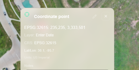
EPSG codes provide standardized identifiers for many coordinate reference systems.
Instead of describing every parameter manually, software can reference a recognized CRS using an identifier.
A familiar example is:
EPSG:4326
This generally refers to WGS 84 geographic latitude and longitude.
Another CRS will use a different EPSG code.
EPSG identifiers make it easier for software and people to communicate exactly which spatial reference is intended.
Why EPSG codes are useful
Imagine telling a client:
The project is in UTM.
That is incomplete.
- Which zone?
- Which datum?
- Northern or southern hemisphere?
Instead, identifying the exact CRS through a recognized EPSG code can remove ambiguity.
The same principle applies to State Plane and other projected systems.
An EPSG code is not the coordinate system itself.
It is an identifier associated with a defined coordinate reference system.
EPSG:4326 versus Web Mercator
Two coordinate systems frequently encountered in web mapping are WGS 84 geographic coordinates and Web Mercator.
EPSG:4326 is commonly associated with latitude and longitude.
Web Mercator is commonly associated with EPSG:3857.
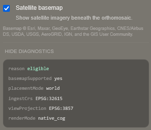
Online basemaps frequently use Web Mercator because it works well for interactive global map display.
This does not mean Web Mercator is necessarily the correct CRS for engineering measurements or professional project delivery.
A web visualization CRS and a project engineering CRS can serve different purposes.
Why CAD files sometimes do not line up
A CAD drawing can contain coordinates without clearly communicating how those coordinates relate to Earth.
Common possibilities include:
- State Plane coordinates
- Local project coordinates
- Arbitrary coordinates
- Feet
- Meters
- A custom engineering coordinate system
- A shifted project origin
If the CAD file and drone mapping dataset use different spatial references, they may not align.
Sometimes the difference is enormous.
Sometimes the error appears as a smaller consistent shift.
The first troubleshooting step should be understanding what coordinate systems both datasets actually use. Construction teams run into this as soon as an ortho is dropped onto a site plan.
Local coordinate systems
Not every project uses a globally recognized CRS.
Some construction and engineering projects use local coordinate systems.
A local system may establish an origin and orientation specifically for one site.
These systems can be extremely useful within a project.
However, converting between a local project system and a broader geographic CRS requires appropriate transformation information.
A drone operator should not guess how that conversion works.
False origins
Projected coordinate systems often use values designed to avoid negative coordinates.
This can result in coordinate values that appear unusually large.
Those numbers are intentional.
They help create convenient coordinate ranges within the projection.
A large easting or northing does not mean the point is physically millions of meters from the project origin in an intuitive local sense.
The coordinate system defines how those values should be interpreted.
Horizontal coordinates versus vertical coordinates
Horizontal location and elevation are related but separate problems.
A project may align correctly in X and Y while being wrong in Z.
This is one of the most common sources of confusion in drone mapping.
Horizontal coordinates answer:
Where is the point across the Earth's surface?
Vertical coordinates answer:
How high is it relative to a defined reference?
The vertical reference needs to be understood separately.
Ellipsoid height
GNSS positioning is mathematically related to an ellipsoid used to model the Earth's shape.
The height measured relative to that ellipsoid is called ellipsoidal height.
This value is not necessarily the same elevation people expect when they think about height above mean sea level.
That distinction becomes extremely important in mapping and construction.
Orthometric height
Orthometric height is the type of elevation commonly associated with height above mean sea level.
It uses a gravitational reference surface related to the geoid.
Survey benchmarks and engineering elevations may be based on an orthometric height system rather than ellipsoidal GNSS height.
In the United States, many engineering elevations are referenced to a named vertical datum such as NAVD 88 rather than to raw GNSS ellipsoid height.
A mapping project can therefore have excellent horizontal positioning while its elevations appear offset if the wrong vertical reference is used.
What is the geoid?
The geoid is a model of an equipotential gravitational surface used as a reference for orthometric heights.
Because Earth's gravity field is not perfectly uniform, the geoid is not identical to a simple mathematical ellipsoid.
Geoid models allow software and survey workflows to relate ellipsoidal GNSS heights to orthometric elevations.
This is why simply reading the Z value from a GNSS position may not produce the same elevation used on a construction plan.
Why elevation mismatches happen
Imagine a drone mapping project aligned perfectly with survey control horizontally.
The orthomosaic looks correct.
The point cloud lines up in plan view.
But every elevation appears consistently too high or too low.
Possible causes include:
- Ellipsoid versus orthometric height
- Different vertical datums
- Wrong geoid model
- Unit mismatch
- Incorrect transformation
- Incorrect benchmark reference
- Processing configuration
- Survey control interpretation
The problem may not be photogrammetry reconstruction at all.
It may be a reference system problem. Drone photogrammetry accuracy explained covers capture and processing quality. Coordinate reference is a separate question.
Horizontal datum versus vertical datum
Horizontal and vertical datums should not be treated as one concept.
The horizontal reference establishes positions across the Earth.
The vertical reference establishes elevation.
A complete professional spatial reference may therefore require documenting both.
This becomes especially important when mapping outputs will be used for:
- Grading
- Earthwork
- Cut and fill
- Drainage
- Design comparison
- Construction verification
- Engineering
- Surveying
Feet versus meters
Unit mismatches can create spectacular errors.
A coordinate may be correct numerically within one system but interpreted incorrectly when software assumes another unit.
Common units include:
- Meters
- International feet
- US survey feet
The difference between meters and feet is immediately significant.
The difference between different definitions of the foot is much smaller, but can still matter in high accuracy professional mapping over sufficiently large distances.
Do not guess the units.
Document them.
US survey foot versus international foot
Historically, some United States geospatial systems used the US survey foot while others used the international foot.
The two definitions are not identical.
For casual mapping the difference may seem insignificant.
For professional coordinate systems and large coordinate values, small unit differences can create measurable discrepancies.
Modern United States geospatial practice has moved toward the international foot, but legacy project data may still use older conventions.
This is another reason the complete CRS definition matters.
Why an orthomosaic can appear shifted
A shifted orthomosaic does not automatically mean the drone mapping failed.
Possible causes include:
- Wrong CRS assigned
- Wrong CRS transformation
- Incorrect datum
- Incorrect UTM zone
- Wrong State Plane zone
- Feet interpreted as meters
- Local coordinates treated as global coordinates
- Control entered using the wrong reference
- Insufficient positioning accuracy
- Incorrect georeferencing
The troubleshooting process should separate coordinate system problems from actual positional accuracy problems.
Assigned CRS versus transformed CRS
This distinction is extremely important.
Assigning a CRS tells software:
These coordinates already belong to this coordinate system.
Transforming or reprojecting data tells software:
Convert these coordinates from one known CRS into another.
Assigning the wrong CRS does not correctly move the data.
It simply tells the software to interpret existing numbers differently.
That can move a dataset to a completely incorrect location.
Reprojection
Reprojection converts geospatial data between coordinate reference systems.
For example, a mapping dataset may be processed in one CRS but delivered in another CRS required by the client.
Proper reprojection uses the known relationship between the source and destination coordinate systems.
Different raster, vector, point cloud, and CAD workflows may handle reprojection differently.
The transformation should be deliberate rather than guessed.
Coordinate transformations
Some conversions involve more than changing the map projection.
Different datums or reference frames may require coordinate transformations.
The required transformation can depend on:
- Location
- Reference system
- Accuracy requirements
- Epoch or realization
- Available transformation grids
- Professional requirements
For demanding surveying or engineering workflows, transformation methodology should follow the project specifications and responsible geospatial professionals.
Coordinate reference systems and GeoTIFF
GeoTIFF can embed geospatial referencing information with raster data.
An orthomosaic GeoTIFF can therefore carry information describing how the raster belongs in geographic space.
This is one reason GeoTIFF is widely used for professional orthomosaic delivery.
A screenshot of the same orthomosaic does not preserve the same spatial reference capability.
The image may look identical but be far less useful for geospatial work. GeoTIFF vs Cloud Optimized GeoTIFF explains how that georeferenced raster can also be organized for remote viewing.
Coordinate systems and LAS or LAZ
Point cloud formats such as LAS and LAZ can also include spatial reference information.
That allows compatible software to understand how millions of XYZ points relate to a real world coordinate system.
Point clouds often contain large coordinate values associated with projected systems.
The receiving software needs the correct CRS to position those points with other project data. See LAS vs LAZ for the file formats themselves, and what a point cloud is if the product is unfamiliar.
Coordinate systems and elevation rasters
DSM and DTM products also require spatial reference.
The raster needs horizontal placement.
Its pixel values may also represent elevations associated with a particular vertical reference.
For earthwork and terrain analysis, both dimensions matter.
A visually correct elevation surface can still produce incorrect comparisons if its vertical reference differs from the design surface. DSM vs DTM vs DEM covers what those rasters contain.
Coordinate systems and cut and fill
Cut and fill is particularly sensitive to coordinate reference problems.
Two surfaces may look similar while containing a vertical offset.
If that offset is interpreted as real terrain change, the resulting calculated volume can be badly wrong.
Before comparing surfaces, verify:
- Horizontal CRS
- Vertical reference
- Units
- Alignment
- Capture dates
- Surface methodology
- Reference surface
Coordinate systems are part of measurement quality.
RTK and coordinate systems
RTK improves GNSS positioning using correction information.
However, accurate positioning still needs to be expressed in the correct reference system.
An RTK capable drone does not remove the need to understand:
- Datum
- Projection
- Coordinate system
- Vertical reference
- Units
- Transformation requirements
RTK addresses positioning quality.
CRS defines how that position is described.
They solve different problems.
Ground control points
Ground control coordinates also belong to a coordinate reference system.
When survey control is provided, the mapper should know:
- Horizontal CRS
- Vertical datum or elevation reference
- Units
- Point identifiers
- Coordinate order
- Control methodology
Entering accurate ground control into the wrong coordinate system can ruin an otherwise strong mapping workflow.
Checkpoints
Independent checkpoints help evaluate how the finished mapping project agrees with known coordinates.
Those checkpoint coordinates also need to use a compatible reference system.
A comparison is meaningless if the mapping surface and checkpoints describe position differently.
Coordinate reference is therefore foundational to accuracy testing.
Repeat drone mapping
Coordinate consistency becomes especially important when mapping the same project repeatedly.
Imagine construction progress flights every week.
If each capture uses a different:
- CRS
- Vertical reference
- Transformation
- Control methodology
- Processing convention
the datasets may not overlay reliably.
Repeat mapping benefits from a documented project coordinate standard. Drone mapping for construction depends on that consistency from visit to visit.
Why one mapping project can have multiple CRSs
Professional workflows sometimes use several spatial references.
For example:
- Drone image GNSS positions may originate in a global geographic reference.
- Processing may use a local projected CRS.
- Engineering CAD may use State Plane.
- A browser map may display data in Web Mercator.
- A client export may use another specified CRS.
This does not necessarily mean something is wrong.
Different stages can use different coordinate representations.
The important requirement is that transformations between them are understood and controlled.
Web maps versus engineering coordinates
Interactive web maps frequently use coordinate systems optimized for global visualization.
Engineering workflows usually prioritize local measurement and project compatibility.
A browser may therefore display a mapping project using a different internal coordinate representation than the native downloadable file.
This is normal when handled correctly.
Visualization format and professional source data do not need to use identical internal representations.
Coordinate metadata should travel with the project
A common delivery mistake is sending files without explaining their spatial reference.
A project should not require the recipient to reverse engineer its coordinate system.
Useful project documentation may include:
- Horizontal CRS name
- EPSG code where applicable
- Datum
- Projection
- Zone
- Horizontal units
- Vertical datum
- Vertical units
- Geoid model where relevant
- Control methodology
- Transformation notes where relevant
Drone mapping deliverables explained is the rest of that package: which files exist, and what each one is for.
What should you ask a surveyor or engineer?
When receiving control or design data, useful questions include:
- What horizontal coordinate system is this project using?
- What datum or realization applies?
- What State Plane or UTM zone applies?
- Are the units feet or meters?
- If feet, which definition is being used?
- What vertical datum is being used?
- Are elevations orthometric or ellipsoidal?
- What geoid model applies?
- Is the CAD file already georeferenced?
- Is the project using a local coordinate system?
- Are there known transformation requirements?
Not every project requires every question.
The goal is to remove ambiguity before capture and processing.
What should you tell your client?
When delivering mapping data, provide enough information for technical users to interpret it correctly.
At minimum, depending on the project, consider documenting:
- Coordinate reference system
- EPSG code where applicable
- Horizontal units
- Vertical reference
- Vertical units
- Capture date
- Positioning method
- Control methodology
- Accuracy information
- File types
- Known limitations
This is especially useful when deliverables will move between different software packages or organizations. Drone operators usually need this list as soon as processing is finished.
Troubleshooting data that does not align
When two spatial datasets fail to align, do not immediately drag one manually until it looks correct.
First investigate:
- Do both files have defined coordinate systems?
- Are those definitions correct?
- Are the datums compatible?
- Are the zones correct?
- Are the units correct?
- Is one dataset using local coordinates?
- Are the vertical references different?
- Was one CRS assigned incorrectly?
- Was reprojection actually performed?
- Is there a real positioning error?
A visual manual adjustment can hide the underlying problem.
Why manual alignment can be dangerous
Moving spatial data until it visually matches another layer may solve a presentation problem while destroying coordinate integrity.
Once manually shifted, the dataset may no longer correspond correctly with:
- Survey control
- CAD
- GIS
- Other captures
- Design surfaces
- Future mapping missions
If a dataset is misaligned, determine why before applying arbitrary transformations.
Coordinate systems do not determine accuracy
Using the correct CRS does not automatically make a mapping project accurate.
Coordinate systems describe how positions are represented.
Accuracy describes how closely those positions agree with reality.
A dataset can use the correct State Plane CRS and still contain poor positioning.
Likewise, a highly accurate dataset can appear completely wrong when assigned the incorrect CRS.
Both problems need to be handled separately.
Geographic, projected, and vertical references
| Concept | What it answers | Typical mapping context |
|---|---|---|
| Geographic CRS | Angular location on an Earth model and datum | GNSS positions, latitude and longitude, EPSG:4326 |
| Projected CRS | Linear easting and northing on a flat plane | UTM, State Plane, many CAD and engineering files |
| Vertical reference | Height relative to an ellipsoid, geoid, or named vertical datum | Ellipsoid height versus orthometric elevation |
| EPSG code | A standardized identifier for a defined CRS | Removing ambiguity about zone, datum, and units |
Assigning a CRS interprets coordinates that already belong to that system.
Reprojecting converts coordinates from one known CRS into another.
Those are different operations.
A practical drone mapping coordinate workflow
A professional mapping workflow may look like this:
- Determine client spatial requirements.
- Identify the horizontal CRS.
- Identify the vertical reference.
- Confirm units.
- Confirm survey control reference.
- Plan RTK, PPK, GCP, and checkpoint methodology where required.
- Capture the site.
- Process using the intended spatial reference.
- Verify control and checkpoints.
- Inspect horizontal alignment.
- Inspect elevations.
- Generate mapping deliverables.
- Export using the required CRS.
- Document the coordinate system.
- Deliver the files with spatial metadata and project context.
The details vary by project, but the principle remains consistent.
Coordinate decisions should happen before final export.
Coordinate systems are part of professional delivery
A technically excellent mapping dataset loses much of its value if the recipient cannot determine where it belongs.
Professional delivery should allow someone opening the project months later to understand:
- Where the data is located
- Which coordinate system it uses
- How elevations are referenced
- How it aligns with other project information
- Which files belong to the same capture
- How the project was positioned
This information becomes even more important when a mapping mission produces multiple spatial deliverables.
An orthomosaic, point cloud, DSM, DTM, CAD file, and design surface all describe parts of the same physical project.
Their coordinate reference is what allows those pieces to occupy the same spatial world.
Understanding CRS, datums, projections, EPSG codes, units, and elevation references is therefore not GIS trivia.
It is fundamental to making drone mapping data useful.